For simplicity, in the above diagram the air locks and the open steel lattice supporting the fuel bundles are not shown.
| Home | Energy Physics | Nuclear Power | Electricity | Climate Change | Lighting Control | Contacts | Links |
|---|
FAST NEUTRON REACTOR (FNR) CONCEPT:
This web page is intended to introduce the subject of Fast Neutron Reactors (FNRs) without reliance on prior knowledge of advanced science or mathematics. This web page briefly outlines what a sodium cooled Fast Neutron Reactor (FNR) is and how it works.
A more mathematically rigerous introduction to sodium cooled FNRs is provided on the web page titled: FNR Introduction.
An overview of FNR related technical topics is provided on the web page titled:
Fast Neutron Reactors.
There are many web pages on this web site that focus on individual components of a sodium cooled FNR power plant.
A more complete description of the science underlying FNRs is set out in the 2021 text by Peter Ottensmeyer titled: Neutrons At The Core.
FNR POWER PLANT:
A practical FNR power plant has four major sections:
a) A protected sodium pool in which passive nuclear physics maintain the liquid sodium at a nearly constant setpoint temperature, typically in the range 450 degrees C to 500 degrees C;
b) A heat transport system which extracts heat from the liquid sodium pool at a controlled rate and safely converts that heat into 10 MPa steam at 400 to 440 degrees C;
c) Remotely located steam turbogenerators that expand and cool the steam to producing electricity and rejecting low grade heat;
d) Cooling towers and a district heating system that dissipate the low grade heat.
MAJOR FNR ADVANTAGES:
A Fast Neutron Reactor (FNR) relies on fast neutrons emitted by nuclear fission. Fast neutrons have initial average kinetic energies of about 2 MeV. The use of fast neutrons in the reactor core gives a FNR major advantages in terms of atmospheric pressure coolant, walk away safety, natural uranium utilization efficiency and elimination of long lived nuclear waste.
MAJOR FNR DISADVANTAGES:
The sodium must always be isolated from water and hot sodium must also always be isolated from air. These isolation requirements restrict the choice of FNR sites and demand a very robust double wall FNR enclosure that enables ongoing maintenance while reliably withstanding hurricanes, tornados, earthquakes and low angle aircraft impacts.
In addition, should the enclosure be breached by a missile, there must be reliable means of quickly extinguishing the resulting sodium fire and of extracting fission product decay heat from the sodium pool.
Complying with these safety requirements significantly adds to the cost of a FNR based nuclear power plant (NPP).
PASSIVE CONTROL OF NUCLEAR HEAT PRODUCTION IN A FNR:
The FNR type described herein consists of a geometrically stable assembly of solid metallic vertical nuclear fuel rods sealed inside 0.375 inch outside diameter chrome steel fuel tubes that are positioned on a (9 / 16) inch square grid. The fuel tubes have a wall thickness of 0.036 inch. Inside each fuel tube is a small amount of liquid sodium which ensures good thermal contact between the metallic fuel rods and the inside wall of the chrome steel tube.
Inside each fuel tube, above the fuel rods, is an empty space known as the plenum, which stores fission product inert gases and which allows for relative thermal expansion of the contained fuel and sodium. The assembly of fuel tubes is entirely immersed in a thermally conductive pool of liquid sodium, comparable in size to a swimming pool.
REACCTIVITY:
The behaviour of the nuclear fuel assembly is characterized by a parameter R known as the reactivity. If R > 0 the rate of nuclear heat production is exponentially increasing. If R < 0 the rate of nuclear heat production is exponentially decreasing. If R = 0 the rate of nuclear heat production is constant.
The reactivity R is a function of the fuel assembly materials, geometry and temperature. The temperature To at which R = 0 is referred to as the reactor setpoint temperature.
The fuel assembly dimensions and materials are also chosen such that the fuel assembly reactivity R versus temperature T curve has a negative slope. Mathematically:
(dR / dT) < 0
Hence, when the fuel assembly temperature T rises above the setpoint temperature To the reactivity R becomes less than zero causing the fuel assembly to soon stop emitting heat. Assuming that there is a constant thermal load removing heat from the sodium pool the fuel assembly will then start cooling. As the fuel assembly temperature T falls below the setpoint temperature To the reactivity again becomes positive causing the fuel assembly to soon emit much more heat. That heat will raise the fuel assembly temperature back toward To. These effects combine to cause the fuel assembly temperature to quickly converge to the setpoint temperature To.
If there is a step increase in reactor thermal load the fuel surface temperature briefly decreases which causes an increase in the reactor reactivity. In response the reactor thermal output power increases. When the increase in reactor thermal output power is sufficient to balance the increase in thermal load the reactor reactivity returns to zero. By this means the reactor keeps its fuel and hence its sodium pool at a nearly constant setpoint temperature To.
Typically the fuel geometry is carefully adjusted so that this fixed setpoint temperature To is in the range 460 degrees C to 500 degrees C. When the liquid sodium temperature drops below the nuclear fuel temperature heat flows by thermal conduction from the nuclear fuel to the liquid sodium until the liquid sodium temperature rises to equal to the nuclear fuel temperature.
AVERAGE FUEL TEMPERATURE MAINTENANCE:
Due to neutron diffusion a FNR will attempt to maintain its average fuel setpoint temperature To. If one end of a fuel rod is cooled then the temperature at the other end of the fuel rod will rise so that the average fuel temperature remains constant at To.
If heat is continuously extracted from the liquid sodium the liquid sodium temperature adjacent to the fuel will be consistently less than To, causing heat to continuously flow from the surface of the nuclear fuel rod to the liquid sodium. To maintain the average fuel rod temperature the fuel rod center line temperature will rise to be greater than To. If there is sodium coolant flowing parallel to the fuel rod the fuel rod temperature will increase along the fuel rod in the direction of sodium flow so that the fuel rod surface temperature increases from the sodium inlet end to the sodium discharge end. That fuel rod temperature distribution will maintain the averge fuel rod temperature To while also result in approximately even heating of the flowing sodium.
In general, if heat is extracted from the sodium pool the nuclear fuel will add an equal amount of heat to the sodium pool to keep the average nuclear fuel temperature constant. If heat extraction from the sodium pool stops the sodium pool temperature will rise to the average nuclear fuel temperature To, at which point the nuclear heat production will stop. This reactor power control process is entirely passive. There are no mechanical moving parts.
As long as the geometry of the fissile fuel assembly remains stable, the sodium pool temperature will remain close to the chosen nuclear fuel setpoint temperature, almost independent of the rate at which heat is extracted from the sodium pool.
FNR POOL GEOMETRY:
The contemplated FNR liquid sodium pool is 20 m diameter X 15 m deep. Centrally positioned in that pool is a fuel assembly with a pancake shaped core zone which contains the heat emitting fissile fuel rods. This core zone is 10 m in diameter X 0.4 m thick. On the diagram the core zone is shown in red.
The core zone is surrounded by a 1.8 m thick blanket of U-238 fuel rods, which on the diagram are shown in pink. The blanket contains U-238 fuel rods, the purpose of which is to absorb neutrons emitted by the core zone. This neutron absorption by U-238 causes formation of fissile atoms within the fertile U-238 fuel rods.
Directly above the upper blanket is the plenum zone, shown in orange on the diagram, which contains top extensions of the fuel tubes but no fuel rods.
During normal reactor operation about half of the fission neutrons produced in the core zone are absorbed within the core zone and the other half of the fission neutrons are mostly absorbed by the surrounding blanket zone.
An important issue in fuel breeding FNR design is neutron conservation. Almost all of the excess neutrons emitted by the core zone should be captured by the surrounding fuel rods in order to breed more fissile fuel. Neutron absorption by other materials should be minimized.
Outside the blankets are guard bands of liquid sodium which absorb any neutrons that escape from the outer surface of the blankets. These guard bands prevent cumulative neutron impingement on the sodium pool walls and sodium pool bottom.
Immersed in the liquid sodium but adjacent to the walls of the sodium pool are intermediate heat exchange bundles which are used to extract useful heat from the sodium pool.
Natural convection of liquid sodium transports heat from the FNR core, up through the upper blanket and plenum zone to the top surface of the sodium pool, radially across the sodium pool top surface, down past the intermediate heat exchange bundles, radially across the pool bottom to the bottom of the fuel tube assembly and then up through the lower blanket to the FNR core.
The reactor core, blanket and plenum dimensions are defined by fuel rod lengths within the assembly of closely spaced vertical fuel tubes. Between adjacent sealed vertical fuel tubes are liquid sodium filled vertical cooling channels. Neutrons in the blanket tend to propagate further vertically than horizontally by following the cooling channels. Hence the thickness of the external liquid sodium guard bands necessary to totally absorb the flux of neutrons which escapes from the blanket is larger above and below the blanket then around the blanket perimeter. Hence the thickness of liquid sodium guard band below the blanket is chosen to be 3 m as compared to 1.9 m around the blanket perimeter.
Above the plenum zone is a 6 m thick layer of liquid sodium containing vertical indicator tubes. The fuel tube plenums and the indicator tubes both contain gas filled spaces that reduce average neutron absorption as compared to pure liquid sodium. Hence, above the upper blanket the sodium guard band thickness is about 7.8 m whereas below the lower blanket the sodium guard band thickness is only about 3 m.
Thus the total depth of the liquid sodium pool is:
3 m (below the blanket) + 1.8 m (lower blanket) + .6 m (core zone) + 1.8 m (upper blanket) + 1.8 m (plenum) + 6 m (indicator tube) = 15.0 m
The diameter of the liquid sodium pool is:
10.0 m + (2 X 1. 8 m blanket) + (2 X 3.2 m guard band) = 20.0 m .
The fuel tube length is:
1.8 m (lower blanket) + 0.6 m (core) + 1.8 m (upper blanket) + 1.8 m (plenum) = 6.0 m
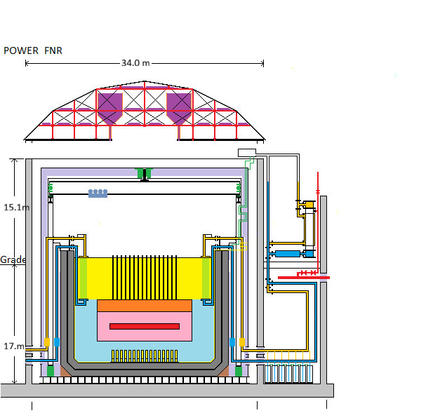
FAST NEUTRON REACTOR SIDE ELEVATION:
For simplicity, in the above diagram the air locks and the open steel lattice supporting the fuel bundles are not shown.
Only 1 of 48 heat transfer loops is fully detailed.
Color Code:
Red - Reactor Core, Steam Main
Pink - Reactor Blanket
Orange- Fuel Tube Plenum
Gold- Warmer NaK pipe
Yellow- hot sodium, hydraulic sodium tube, hydraulic lifter
Light Green - Intermediate Heat Exchange tubes
Dark Green - Hot wall thermal brake support, polar gantry bearins
Light Purple - Fiber Ceramic Insulation
Dark Purple - NaCl Reservoir
Light Blue- cool sodium
Dark Blue - Cooler NaK Pipe
Light Gray - Concrete
Dark Gray - Fire Brick
Black - Steel Outline
REACTOR OPERATION DESCRIPTION:
A modular liquid sodium cooled FNR, such as is described on this web site, consists of a 20 m inside diameter X 15 m deep sodium pool in which are immersed both fuel bundles and intermediate heat exchange bundles. Outside the pool are factory fabricated and tested support modules for heat transport and electricity generation. The fuel bundles, heat exchange bundles and the support modules are all individually road truck portable, both before and after use.
The sodium pool walls and the intermediate heat exchange bundles are protected from neutron impingment and hence do not become significantly radioactive.
The FNR fuel assembly described on this web site has both core and blanket zones. The core zone contains TRU and U-238 atoms and is where the nuclear chain reaction takes place. The blanket zone surrounds the core zone with U-238 atoms that absorb fission neutrons which escape from the core zone. Excess fission neutrons are also absorbed by U-238 atoms in the core fuel rods. After a short delay the resulting U-239 atoms spontaneously transmute through Np-239 to form new Pu-239 and some Pu-240 atoms. These TRU atoms are then either fissioned in the core or are later recovered from the core and blanket via fuel rod reprocessing and are used to make new FNR core fuel rods. In this process the Pu-240 concentration is sufficiently high that the Pu-239 produced cannot be used to make practical nuclear weapons.
The FNR fuel assembly described herein consists of a disk shaped ~ 10.0 m diameter X ~ 0.4 m thick core which is surrounded by a 1.8 m thick blanket. The core contains fuel rods with a mixture of both fissile (potentially neutron emitting Pu-239 atoms) and fertile neutron absorbing U-238 atoms. The blanket initially contains fuel rods with only fertile neutron absorbing U-238 isotope atoms.
The resulting disk shaped fuel assembly is mounted, disk axis upright, in the middle of a 20 m diameter X 15 m deep pool of liquid sodium and is supported 3 m above the sodium pool bottom by an open steel lattice structure. There are many thousands of small flow channels which pass through the fuel assembly to allow liquid sodium to flow vertically for heat removal. The maximum safe thermal output of a FNR is limited by the properties of its fuel and fuel tubes.
The reactivity of the fuel assembly has a negative temperature coefficient. With no thermal load the thermal power is constant so the reactivity is zero. Hence the reactor is at its setpoint temperature To.
If there is a step increase in reactor thermal load the fuel temperature briefly decreases which causes an increase in the reactor reactivity. In response the reactor thermal output power increases. When the increase in reactor thermal output power is sufficient to balance the increase in thermal load the reactor reactivity returns to zero. By this means the reactor keeps its fuel and hence the sodium pool at a nearly constant temperature To.
If there is no thermal load and no fission product decay heat the liquid sodium pool temperature will gradually rise to:
To = 460 degrees C
and then stop.
FNR POWER CONTROL:
Heat is removed from the intermediate heat exchange bundles via isolated NaK loops. The FNR thermal power output is controlled by controlling the NaK flow rate.
REACTOR SETPOINT ADJUSTMENT:
There is a facility for occasional fine adustment of the reactor geometry while the reactor is operating to compensate for fuel and fuel tube aging. This facilty enables adjustment of the FNR temperature setpoint.
FUEL CYCLE:
Provided that the fuel geometry remains stable and the sodium remains clean and is completely isolated from both air and water this energy production process, which involves no moving mechanical parts and no ongoing chemical changes, is extremely stable. One nuclear fuel load can potentially power the reactor for about 30 years during which time about 15% of the reactor core fuel mass is converted into short lived fission products. In order to expedite fuel reprocessing a 20% fuel change is contemplated every six years.
WALK AWAY SAFETY:
If there is any unanticipated problem the reactor defaults into a safe walk away state with the sodium pool at it last temperature setpoint.
This web page last updated November 25, 2023.
| Home | Energy Physics | Nuclear Power | Electricity | Climate Change | Lighting Control | Contacts | Links |
|---|